
RTTY FSK
the FSK connection
When transmitting RTTY using FSK, the transceiver generates a Mark frequency or a Space frequency in response to an external signal. Transceivers capable of FSK operation generally provide a TTL input (voltage levels +5 VDC, 0 VDC) that controls the frequency generation:
Transceiver
FSK Mode Name
FSK Input Signal (connector & pin)
FSK Input Signal Mark Voltage *
FSK Input Signal Space Voltage *
Elecraft K3
FSK D
FSK IN (ACC pin 1)
0 VDC
+5 VDC
Icom
RTTY
RTTY (ACC-1 pin 1) *
*
*
Kenwood TS-590
FSK
RTTY (ACC2 pin 2)
+5 VDC
0 VDC
Kenwood TS-990
FSK
RTTY (ACC2 pin 2)
+5 VDC
0 VDC
Kenwood TS-2000
FSK
RTTY (ACC2 pin 2)
+5 VDC
0 VDC
TenTec Omni-VII
FSK
MARK/SPACE (ACC 1 pin 5)
+5 VDC
0 VDC
TenTec Orion II
FSK
MARK/SPACE (I/O pin 8)
+5 VDC
0 VDC
Yaesu FT-450
RTTY
FSK IN (DATA pin 4)
+5 VDC
0 VDC
Yaesu FT-950
RTTY
FSK IN (RTTY/PKT pin 4)
+5 VDC
0 VDC
Yaesu FT-1000MP MARK-V
RTTY
SHIFT (RTTY pin 1)
+5 VDC
0 VDC
Yaesu FT-2000
RTTY
SHIFT (RTTY pin 1)
+5 VDC
0 VDC
Yaesu FTDX-101
RTTY
SHIFT (RTTY/DATA pin 4)
+5 VDC
0 VDC
Yaesu FTDX-1200
RTTY
FSK IN (RTTY/DATA pin 4)
+5 VDC
0 VDC
Yaesu FTDX-3000
RTTY
FSK IN (RTTY/PKT pin 4)
+5 VDC
0 VDC
Yaesu FTDX-5000
RTTY
SHIFT (RTTY pin 1)
+5 VDC
0 VDC
Yaesu FTDX-9000
RTTY
SHIFT (RTTY pin 4)
+5 VDC
0 VDC
* Notes:
- By convention, amateur RTTY uses the lower sideband, with the Mark frequency 170 hz higher than the Space frequency.
- Icom transceivers
some Icom transceivers transmit the Mark frequency when the FSK Input Signal is set +0 VDC, but other models transmit the Space frequency when the FSK Input Signal is set to 0 VDC
Icom transceivers provide a separate connector for the FSK Input Signal
the IC-7100, IC-7610, IC-7851, IC-9100 drivers create two virtual serial ports: one virtual port is used for transceiver control, and the other virtual port can convey the FSK signal via a second virtual serial port's RTS or DTR signal
virtual serial ports for transceiver control and FSK generation are only created if the transceiver is connected to your computer via a standard USB A-B cable
to determine which virtual port is which, see section 3 of Icom's Tips for the USB Port Settings manual
the transceiver provides a menu item that determines whether the virtual port's RTS or DTR signal is used to convey the FSK signal
the IC-7300 and IC-705 drivers create a single virtual serial port for transceiver control whose RTS or DTR signal can be configured to convey the FSK signal via the radio's USB Keying (RTTY) menu; if this port is being used by Commander for transceiver control, however, its RTS or DTR signal cannot be used as the FSK connection unless you
employ a serial port splitter that creates a virtual port X for transceiver control and a virtual port Y for RTS or DTR control, both of which interact with your IC-7300's virtual serial port
- configure Commander to use virtual serial port X
configure WinWarbler to use virtual serial port Y for FSK control in step 7a in the Configuring WinWarbler for FSK operation section below
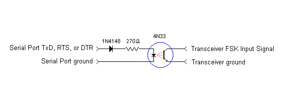
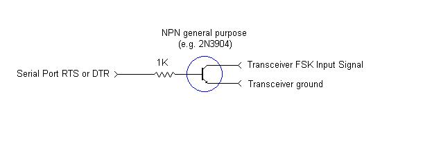
In most transceivers, the FSK Input Signal input is connected to a "pull up" resistor connected to +5 VDC. An NPN transistor, opto-isolator, or open-collector logic gate can thus be used to pull the FSK Input Signal down to 0 VDC, as is shown in the examples below.
Some transceivers provide a menu setting or internal switch that reverses the meaning of the FSK Input Signal voltage. Alternatively, you can reverse the meaning of the FSK Input Signal voltage by checking the Inv. FSK box on the EXTFSK or EXTFSK64 window (accessible via the Windows Task Bar when WinWarbler is configured to transmit RTTY via the MMTTY engine in FSK).
WinWarbler can be configured to generate the FSK Input Signal on the PTT serial port's TxD pin, or on the TxD, RTS, or DTR pin of any available serial port. All of these pins employ RS-232 voltage levels (+12 VDC, -12 VDC), so an external level converter is required:
a simple PNP transistor circuit for the Kenwood TS-930 and TS-940
a series resistor for the TenTec Omni V, VI, and VI+
MORTTY - a CW and RTTY interface
a section of a commercial interface (Interfaces known to work with 32-bit and 64-bit flavors of Windows 7 and Vista); if your interface is aNavigator: see the document entitled Winwarbler RTTY Setup.pdf in this Yahoo group Files area
Everything You Need to Know About USB and Serial Interfaces de N6TV
Configuring WinWarbler for FSK operation
WinWarbler can be configured to generate the FSK signal on the TxD, RTS, or DTR pins of any available serial port. If you are using a USB-to-serial-port adapter and will be configuring WinWarbler to generate the FSK signal on the TxD pin, then this USB-to-serial-port adapter must support 5-bit operation at 45 baud, and you must configure the MMTTY engine to transmit characters at a rate that the USB-to-serial-port adapter can handle:
set the Main window's Operating Mode panel is set to RTTY
on the Configuration window's RTTY tab,
check the Enabled box
in the Modulation and transceiver mode panel's FSK sub-panel
select LSB
set the LSB Xcvr Mode selector to RTTY
set the LSB Mark Offset to -2125
set the Optimal Offset to 2210
set the FSK Control selector to ExtFSK (if running on a 32-bit flavor of Windows) or ExtFSK64 (if running on a 64-bit flavor of Windows
click the MMTTY Setup button
on the MMTTY Setup window's Misc tab
set the Tx port panel to COM-TxD (FSK)
click the USB Port button
in the USB Port Option window, select the C: Limiting Speed option and click the OK button to close the window
close the MMTTY Setup window by click the OK button in its lower-right corner
Set the Main window's Operating Mode panel to RTTY with the Enabled box checked on the Configuration window's RTTY tab; an EXTFSK icon will appear in the Windows Task Bar along the bottom of your monitor (it may be included in the RTTY icon already present there, in which case you must click the RTTY icon to gain access to the EXTFSK icon).
Click the EXTFSK icon in the Windows Task Bar to open the EXTFSK window; in this window,
set the Port selector to the desired serial port
set the FSK output panel to TxD, RTS, or DTR - whichever is being used to control Mark/Space frequency switching (if using a USB-to-serial-port adaptor that doesn't support 5-bit operation at 45 baud, choose RTS or DTR)
The EXTFSK icon will appear in the Windows Task Bar whenever you operate in soundcard RTTY mode, but it will remember the settings you've established, so subsequently opening the ESTFSK window is unnecessary.
To use the PTT serial port's TxD pin to control Mark/Space frequency switching, open the Configuration window's PTT tab and note the serial port selected in the PTT panel's Port tab. Select the Configuration window's RTTY tab, and in the Modulation and transceiver mode panel's FSK section,
click the LSB button
set the FSK Control selector to the same serial port selected in Port panel on the Configuration window's PTT tab
If necessary, you can change the COM port number that Windows assigns to a USB-to-serial-port adaptor.
Debugging
When a transceiver is configured to transmit RTTY via FSK, its transmitter sends either Mark or Space tone as dictated by the voltage level of a single input, variously named FSK IN or RTTY or MARK/SPACE or SHIFT. Directing WinWarbler to switch from receiving to transmitting without specifying any characters to be transmitted will result in the transmission of a continuous sequence of diddle characters - each composed of a single start bit (Space tone) followed by 5 data bits, all of which are Mark tone; audibly, the result is a recognizable warbling between the Mark and Space tones.
If instead of diddles, you hear a single tone, that means your transceiver's FSK IN or RTTY or MARK/SPACE or SHIFT input signal is not being correctly driven. To determine why, work backwards from that input signal:
- the cable between the input signal and the interface that generates the signal is broken in the middle, or one of its two connectors is damaged
- the interface that generates the signal is not working, either because it's not powered, or is defective
- the interface the generates the signal is working, but is not receiving appropriate directives from the application that controls it because
- the cable between the interface and computer is broken in the middle, or one of its two connectors is damaged
WinWarbler is not properly configured, e.g. wrong serial port, or wrong modem control signal
If WinWarbler is configured as described in the section above but you're still hearing a single tone when transmitting RTTY FSK, then focus on items 1 through 3a. An oscilloscope will enable you to trace the signals backward from the transceiver input; since FSK signaling occurs at 45.45 baud, even an old oscilloscope whose fastest sweep rate is 50 KHz will be useful.
Post a question or suggestion on the DXLab Discussion Group
Transmitting RTTY FSK with TinyFSK
Setting up CW, Phone, PSK, and RTTY Operation