|
|
Commander Online Help Contents
Increasingly, modern radios provide for computer control beyond VFO, mode, and filter selection. To provide access to these capabilities, Commander lets you specify
up to 33 Command Sequences, each containing up to 64 transceiver commands
up to 16 Command-generating Sliders
To enable access to all Command Sequences and Command-generating Sliders, check the Show by expanding Main window box in the User-defined Controls panel on the General tab of Commander's Configuration window; Commander's Main window will be expanded in height to display a panel containing two rows of eight buttons and two rows of four horizontal slider controls; if you don't need all four rows of buttons and sliders, you can adjust the bottom border of Commander's Main window upward by dragging it with the left mouse button depressed. Alternatively, you can check the Show within Main window box, which will
display a User-defined Controls panel containing 8 buttons and 4 sliders that can be used to invoke and edit User-defined Controls - setting Commander's Main window to its standard height
disable all three Frequency-dependent device panels
Each Command Sequence can optionally display a "LED-like display" beneath its button, and specify this LED's color.
If you specify Command Sequences or Command-generating Sliders, and are controlling more than one transceiver, you must specify a User-defined Control Set for each transceiver.
A Command Sequence specifies 64 commands, where each command can accomplish one of several things:
convey an instruction to your transceiver (CAT)
terminates execution of the sequence
conditionally or unconditionally change the flow of control within the sequence
do nothing
update the caption shown on the button used to activate the sequence
specify the text font color, text font bold property, and surface color of the button used to activate the sequence
specify the color displayed by an LED the button used to activate the sequence
update the contents of the explanatory popup window that appears when the mouse cursor hovers over the button used to activate the sequence
Command Sequences are numbered 1 through 32, and organized as two banks of sixteen sequences. Two rows of eight buttons are used to activate the sequences in the current bank; you can also activate sequences in the current bank by striking the F5 through F12 function keys for the bank's first row of eight sequences, and SH-F5 through SH-F12 function keys for the bank's second row eight sequences (depress this SHIFT key while striking a function key between F5 and F12). The ALT checkbox located between the sequence buttons determines which bank is current. To switch banks, check or uncheck the ALT checkbox. Depressing the ALT key while clicking a sequence button or striking one of F5 through F12 activates a sequence in the first row of the second bank; depressing the ALT key while clicking a sequence button or depressing both the ALT and SHIFT keys while striking one of F5 through F12 activates a sequence in the second row of the second bank
An Initial Command Sequence can be optionally executed when Commander starts, or when a new radio Model is selected. To define, edit, or test this sequence, click the Edit button in the Initial Command Sequence Panel on the Config window's General tab.
A
specified
Command Sequence can be executed
when you change bands by clicking a button
in the Band panel at the bottom
of Commander's Bandspread window.
A
specified
Command Sequence can be executed
when you change
mode.
A specified Command Sequence can be executed when you activate a memory by clicking a Sel button in the Memory Bank panel on Commander's Main window.
A specified Command Sequence can be executed when a Command-generating Slider's value changes.
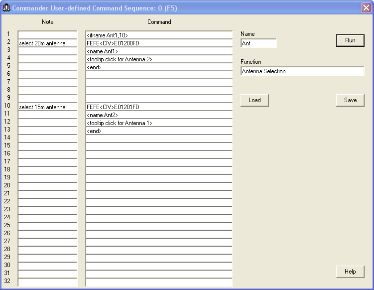
To define, edit, or test a Command Sequence for a button in the User-defined Controls panel, right-click the button; you can also depress the CTRL key while clicking that button or while striking it's associated function key (F5 through F12, as designated above each button). To define a Command Sequence in the second bank, check the ALT box and then right-click the appropriate button, or depress both the ALT and CTRL keys while clicking on the button or while striking its associated function key. Commander will display a window that enables you to name and document a sequence of up to 32 radio commands to be sent to your transceiver when the associated Command Sequence button is clicked, when its associated function key is struck, or when a directive is received from another application (e.g. WinWarbler). Each Command Sequence is composed by a list of 32 Commands and Notes, a Name, and a Function:
| Name | specifies the
name of the sequence; this name serves as the caption on the associated
User-defined Command Sequence button, so choose a name of
appropriately-short length
Note: if you wish to include the ampersand character in the name, use a pair of back-to-back ampersands, e.g. R&&B. |
| Button Colors |
|
| Commands |
|
| LED Display | if the Enabled box is checked, a LED-like display appears beneath the associated User-defined Command Sequence button; the color displayed by this LED is specified by the Initial Color selector |
| Function | describes the function of the Command Sequence; this information will appear in a popup explanation window when the mouse cursor lingers above the associated Command Sequence button if the display of control explanations is enabled. |
| Command (1-32) | a sequence of radio commands to be executed, beginning with Command 1 |
| Note (1-32) | optional information used to document the associated command; this information is not sent to your radio |
Valid commands are enumerated in the following table:
| Command | Function | |||||||||||||||||||||||||||||||||||||||||||||||||||
| an even number of
hexadecimal characters, e.g.
FEFE26E00700FD |
hexadecimal radio
command -- characters are sent to your
radio via the primary CAT serial
port,
two per byte (useful for Icom, TenTec, and older Yaesu radios)
|
|||||||||||||||||||||||||||||||||||||||||||||||||||
| a sequence of ascii characters preceded by a
single apostrophe, e.g.
'AN1; |
ASCII radio
command -- each character following the apostrophe will be
sent to your radio via the
primary CAT serial port (useful for Kenwood, Elecraft, and recent
Yaesu radios)
|
|||||||||||||||||||||||||||||||||||||||||||||||||||
| a sequence of ascii characters preceded by a
single tilde, e.g.
~slice set 0 rxant=ant1 |
ASCII radio
command -- each character following the tilde will be
sent to your radio via the TCP/IP connection (useful for Flex
Signature radios)
|
|||||||||||||||||||||||||||||||||||||||||||||||||||
| <Band mHz> | activates
the Bandspread window's Band
Stack for the specified band, setting the radio's frequency to the
most recent frequency used on that band, setting its mode to the mode in
use at that time, and clearing Split
For example, the command <Band 14> will QSY to the most recent 20m frequency and mode, and clear Split. |
|||||||||||||||||||||||||||||||||||||||||||||||||||
|
<ButtonTextBold
On> <ButtonTextBold Off> |
sets the current Command Sequence's button text bold property to on or off | |||||||||||||||||||||||||||||||||||||||||||||||||||
|
<ButtonTextColor
color>
|
sets the
current Command Sequence's button text color to color
|
|||||||||||||||||||||||||||||||||||||||||||||||||||
| <ButtonTextColor Q, color> |
sets the
specified Command Sequence's button text color to color
|
|||||||||||||||||||||||||||||||||||||||||||||||||||
| <ButtonSurfaceColor color> |
sets the
current Command Sequence's button surface color to color
|
|||||||||||||||||||||||||||||||||||||||||||||||||||
| <ButtonSurfaceColor Q, color> |
sets the
specified Command Sequence's button surface color to color
|
|||||||||||||||||||||||||||||||||||||||||||||||||||
|
<DataSignalsEnable
On>
<DataSignalsEnable Off> |
<DataSignalsEnable
On> checks the Parallel Port Data
Signals panel's Enable box, thereby enabling frequency-based control
of the parallel port data output.
<DataSignalsEnable Off> un-checks the Parallel Port Data Signals panel's Enable box, thereby disabling frequency-based control of the parallel port data output. When the value of the Parallel Port Data Signals panel's Enable box is changed by either of these commands, the new Enable box setting is not saved in the Windows Registry. |
|||||||||||||||||||||||||||||||||||||||||||||||||||
| <Dual
On>
<Dual Off> |
enables or disables the current transceiver's Dual Receive | |||||||||||||||||||||||||||||||||||||||||||||||||||
| <End> | termination
|
|||||||||||||||||||||||||||||||||||||||||||||||||||
| <FreqDepDevEnable
On, N>
<FreqDepDevEnable Off, N> |
<FreqDepDevEnable
On, N> enables Frequency-dependent
Device N, where N is a number the range of 0 to 3.
<FreqDepDevEnable Off, N> disables Frequency-dependent
Device N, where N is a number the range of 0 to 3.
|
|||||||||||||||||||||||||||||||||||||||||||||||||||
| <Goto N> | unconditional
branch
|
|||||||||||||||||||||||||||||||||||||||||||||||||||
| <IfBand bandname, N> | conditional
branch based on the current transceiver's current band
|
|||||||||||||||||||||||||||||||||||||||||||||||||||
| <IfButtonTextBold N> |
conditional branch based on the Command Sequence's current bold button
text property
|
|||||||||||||||||||||||||||||||||||||||||||||||||||
| <IfLED color, N> | conditional
branch based on the Command Sequence's current LED color
|
|||||||||||||||||||||||||||||||||||||||||||||||||||
| <IfMode modename, N> | conditional
branch based on the current transceiver's mode as last reported to
Commander
|
|||||||||||||||||||||||||||||||||||||||||||||||||||
| <IfName name, N> | conditional
branch based on the Command Sequence's current button caption
|
|||||||||||||||||||||||||||||||||||||||||||||||||||
| <IfRadioName name, N> | conditional
branch based on the current primary transceiver's name
|
|||||||||||||||||||||||||||||||||||||||||||||||||||
| <IfSeqName Q, name, N> | conditional
branch based on the specified Command Sequence's current button caption
|
|||||||||||||||||||||||||||||||||||||||||||||||||||
| <IfSplit N> | conditional
branch based on whether the current transceiver is operating split
|
|||||||||||||||||||||||||||||||||||||||||||||||||||
| <LED color> | sets the
current Command Sequence's LED color to color
|
|||||||||||||||||||||||||||||||||||||||||||||||||||
| <LED Q, color> | sets the
specified Command Sequence's LED color to color
|
|||||||||||||||||||||||||||||||||||||||||||||||||||
| <LED QF:QL, color> | sets the
specified range of Command Sequence LED colors to color
|
|||||||||||||||||||||||||||||||||||||||||||||||||||
| <Mode modename> | sets the
current transceiver's mode to modename
|
|||||||||||||||||||||||||||||||||||||||||||||||||||
| <Name text> | sets the current Command Sequence's button caption to text | |||||||||||||||||||||||||||||||||||||||||||||||||||
| <Name Q, text> | sets the
specified Command Sequence's button caption to text
|
|||||||||||||||||||||||||||||||||||||||||||||||||||
| <ParData N> | sets the specified parallel port's eight data bits (pins 9 through 2) to the least significant 8 bits of N | |||||||||||||||||||||||||||||||||||||||||||||||||||
| <ParClearBit B> | clears the
specified parallel port's data bit B
|
|||||||||||||||||||||||||||||||||||||||||||||||||||
| <ParSetBit B> | sets the
specified parallel port's data bit B
|
|||||||||||||||||||||||||||||||||||||||||||||||||||
| <PriDTR On>
<PriDTR Off> |
enables or disables the Primary CAT Port's DTR modem control signal | |||||||||||||||||||||||||||||||||||||||||||||||||||
| <PriRTS On>
<PriRTS Off> |
enables or disables the Primary CAT Port's RTS modem control signal | |||||||||||||||||||||||||||||||||||||||||||||||||||
| <priXcvr N> | selects primary radio N | |||||||||||||||||||||||||||||||||||||||||||||||||||
| <QSY +F> | increases the current transceiver's frequency by F KHz, e.g. <QSY +1> | |||||||||||||||||||||||||||||||||||||||||||||||||||
| <QSY -F> | decreases the current transceiver's frequency by F KHz, e.g. <QSY -2> | |||||||||||||||||||||||||||||||||||||||||||||||||||
| <QSY freq> | sets the current transceiver's frequency to Freq KHz, e.g. <QSY 14200> | |||||||||||||||||||||||||||||||||||||||||||||||||||
| <Receive> | directs the radio to switch from transmitting to receiving (equivalent to clicking the RX button) | |||||||||||||||||||||||||||||||||||||||||||||||||||
| <Reset> | resets communications with the primary transceiver and then re-initializes it | |||||||||||||||||||||||||||||||||||||||||||||||||||
| <SetDeviceDataFile N, pathname> | if pathaname exists, sets frequency-dependent device N's Data File to that pathname and directs that device to its Device Table from that pathname | |||||||||||||||||||||||||||||||||||||||||||||||||||
| <Slider S, V> | sets a
specified slider to a
specified value
|
|||||||||||||||||||||||||||||||||||||||||||||||||||
| <SO2R text> |
if the SO2R Serial Port is Enabled, sends the text followed by a carriage return (ascii 13) to the SO2R Serial Port |
|||||||||||||||||||||||||||||||||||||||||||||||||||
| <SpectrumFixedRange L,U> |
when controlling a radio with a Spectrum-Waterfall window enabled and in Fixed mode, sets the range's lower bound to L and the range's upper bound to U, where L and U are specified with one of 5 formats:
|
|||||||||||||||||||||||||||||||||||||||||||||||||||
| <SpectrumMode M> |
when controlling a radio with a Spectrum-Waterfall window enabled,
|
|||||||||||||||||||||||||||||||||||||||||||||||||||
| <SpectrumRefLevel R> | when controlling a radio with a Spectrum-Waterfall window enabled, sets the curent Reference Level to R db without changing the reference level associated with the current band or sub-band | |||||||||||||||||||||||||||||||||||||||||||||||||||
| <Split
On>
<Split Off> |
enables or disables the current transceiver's Split | |||||||||||||||||||||||||||||||||||||||||||||||||||
| <Tooltip text> | sets the current Command Sequence button's popup explanation to text | |||||||||||||||||||||||||||||||||||||||||||||||||||
| <Tooltip Q, text> | sets the
specified
Command Sequence button's popup explanation to text
|
|||||||||||||||||||||||||||||||||||||||||||||||||||
| <Transmit> | directs the radio to switch from receiving to transmitting (equivalent to clicking the TX button) | |||||||||||||||||||||||||||||||||||||||||||||||||||
| <TXMeter MeterName> | sets the Xmit Meter selector to the specified MeterName | |||||||||||||||||||||||||||||||||||||||||||||||||||
|
<UDPAntSelEnable On> <UDPAntSelEnable Off> |
enables
inclusion of the specified
Antenna name in
Radio Info messages sent to active UDP connections disables inclusion of the specified Antenna name in Radio Info messages sent to active UDP connections |
|||||||||||||||||||||||||||||||||||||||||||||||||||
| <UDPAntSelName text> | specifies the Antenna name in Radio Info messages sent to active UDP connections | |||||||||||||||||||||||||||||||||||||||||||||||||||
| <UDPAuxAntSelEnable
On> <UDPAuxAntSelEnable Off> |
enables
inclusion of the specified
Auxiliary
Antenna number and
Auxiliary Antenna
name in
Radio Info messages sent to active UDP connections disables inclusion of the specified Auxiliary Antenna number and Auxiliary Auxiliary Antenna name in Radio Info messages sent to active UDP connections |
|||||||||||||||||||||||||||||||||||||||||||||||||||
| <UDPAuxAntSelNumber text> | specifies
the Auxiliary
Antenna number in
Radio Info messages sent to active UDP connections |
|||||||||||||||||||||||||||||||||||||||||||||||||||
| <UDPAuxAntSelName text> | specifies the Auxiliary Antenna name in Radio Info messages sent to active UDP connections | |||||||||||||||||||||||||||||||||||||||||||||||||||
| <UDPSendRadioInfo> | directs Commander to send a Radio Info message bearing the primary transceiver's frequency, mode, and other informationto active UDP connections | |||||||||||||||||||||||||||||||||||||||||||||||||||
| <XcvrA=B> | directs the radio to set the VFO B (or sub-receiver) frequency to the VFO A (or main receiver) frequency | |||||||||||||||||||||||||||||||||||||||||||||||||||
| <XcvrAxB> | directs the radio to exchange the VFO A (or main receiver) and VFO B (or sub-receiver) frequencies | |||||||||||||||||||||||||||||||||||||||||||||||||||
| <Wait> | pauses for the duration indicated in the Command Interval textbox after executing the previous transceiver command in the sequence before executing the next transceiver command in the sequence. |
The conditional branch and sequence button naming commands make it possible to create sequences that toggle a sequence button's function, as shown in this simple example for the Icom IC-7300 that alternately enables and disables the Noise Blanker, and uses the LED color to display the Noise Blanker's current state:
|
|
The Load and Save buttons enable you to load a Command Sequence from a specified file and save a Command Sequence to a specified file, respectively. The Sequence file panel displays the pathname of the file from which this sequence was most recently loaded or from which it was most recently saved; to specify a different pathname, click the Load or Save button.
Do not attempt to modify a Command Sequence by editing a file created by clicking the Save button. To edit the Command Sequence associated with a button in the User-defined Controls panel, right-click that button.
If you are controlling multiple primary transceivers, you can define a user-defined control set that specifies the Command Sequences to be loaded when you switch among primary transceivers.
Substitution strings let you insert the value of a command-generating slider, CI-V address, or ascii character into a specified position within a radio command.
The insertion of a slider's value into a template instruction is specified via a substitution string of the form <SFN>, where
For example, the command FEFE6EE01401<2D4>FD will use the current value of slider 2 to set an Icom 756 Pro III's AF gain. The S is only optional when the substitution string appears in the Command of a command-generating slider's Configuration window; in this case, the slider's own value is used, as shown in the screenshot in the section below.
The substitution string <CIV> is replaced hexadecimal radio commands by the current transceiver's specified CI-V address. Thus, the command FEFE<CIV>E01401<2D4>FD will be executed by the transceiver whose CI-V address is specified in the Radio panel on the Configuration window's General tab.
When controlling a Flex Signature transceiver, the substitution string <FlexSigPanStream> is replaced by the hexadecimal ID of VFO A's panadapter. This ID is required by some of the commands used to control a Flex Signature transceiver.
The substitution string <n> (where n is an integer between 0 and 127) is replaced in ASCII radio commands by a single character whose ascii value is n; for example, <13> will be replaced by the "carriage return" character.
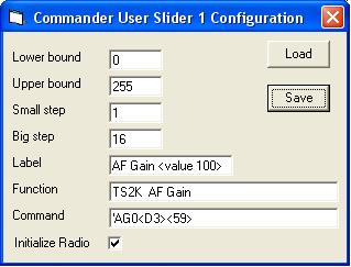
One can set the AF gain of a Kenwood TS-2000 by sending it the ASCII command AG0NNN; where NNN is a 3-digit decimal number between 0 and 255 that specifies the desired gain. One can set the AF gain of an Icom 756 Pro III by sending it the hexadecimal command FEFE6EE01402XXXXFD when XXXX is a 4-digit decimal number between 0 and 255. A Command-generating Slider lets you "fill in" the NNN or XXXX with an appropriate value determined by the handle position of a horizontal slider control in Commander's User-defined Commands panel. To control a TS-2000's AF gain with a slider control, one must at minimum configure the slider with
This information is captured by the User Slider Configuration window, which can be made to appear by double-clicking the label beneath the Slider control:
|
The <D3> substitution command does not specify a Slider number, so Slider 1's value is used (because this is Slider 1's configuration) |
|
A Slider's value is changed by
dragging it's handle left or right,
clicking its left-arrow or right-arrow
clicking the space to the left or right of its handle
executing a <slider> command in a Command Sequence
a frequency-dependent device control configured to drive the slider
receiving a directive from another application (e.g. WinWarbler).
In the example shown in the above screenshot of Commander User Slider 4's Configuration window, the ASCII command AG0000; will be generated when slider 4's handle is moved to the extreme left, the ASCII command AG0255; will be generated when slider 4's handle is moved to the extreme right, and the ASCII command AG0128; will be generated when slider 4's handle is centered.
Note that while the CI-V commands used to control Icom transceivers are expressed in hexadecimal, variable settings must often be expressed in decimal. For example, the template used to control an Icom 756 Pro III's AF gain with slider #2 is FEFE6EE01401<2D4>FD (with a lower bound of 0 and an upper bound of 255) . In contrast, using slider #5 to select a Yaesu FT-1000MP's mode would be accomplished with 000000<5H>0C (with a lower bound of 0 and an upper bound of 11).
Only the signed decimal and hexadecimal formats should be used with sliders that can take on negative values. For example, the FlexRadio template 'ZZWB<1S4> will generate commands like ZZWB+028 or ZZWB-014 .
Commander's 16 Sliders are numbered 1 through 16 and organized into two banks of 8, which each bank containing two rows of 4 sliders. The same ALT checkbox that switches between banks of Command Sequences also switches between banks of sliders.
When clicked, the Save button saves the slider definition to a file you specify; the slider definition includes the slider's current value. The Load button loads the slider definition from a file you specify and sets the slider to the value saved in the file.
The Load and Save buttons enable you to load a Slider from a specified file and save a Slider to a specified file, respectively. The Slider file panel displays the pathname of the file from which this sequence was most recently loaded or from which it was most recently saved; to specify a different pathname, click the Load or Save button.
If you are controlling multiple primary transceivers, you can define a user-defined control set that specifies the Command-generating Sliders to be loaded when you switch among primary transceivers.