WinWarbler External Modem Settings
WinWarbler Online Help
Contents
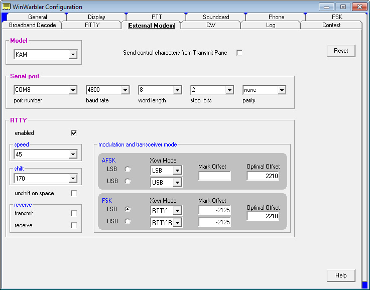
The External Modem tab provides settings that control
operation when WinWarbler is sending and receiving RTTY or CW via an external
modem connected to your PC via a serial port, via a transceiver controlled by
Commander, or via another application. (screen
shot).
The model selector lets you
choose the external modem model from among those for which external modem
command
files are present in WinWarbler's Modems
subfolder. WinWarbler includes files for the KAM,
MFJ464,
PK232, PK900,
PTCII, and TinyFSK.
WinWarbler also includes
-
a file named Decoder App.txt
that contains no command definitions for use with external decoders whose
output is conveyed via command sent to WinWarbler
-
a file named External.txt
that contains no command definitions for use with external decoders whose output
is conveyed via an RS-232 port - including transceivers like the IC-7700 and
IC-7800.
-
a file named Xcvr
Ctrl App.txt that contains no command definitions for use
with transceivers like the K3 and KX3, whose CW and RTTY decoder output is
conveyed via commands sent by Commander to WinWarbler
You can modify the provided command files, or create files for other modem models using a simple command
syntax.
The send
control characters from Transmit Pane box, when checked, routes
control characters struck in the Transmit Pane other than CTRL-J, CTLR-Q,
CTRL-R, CTRL-S, and CTRL-V to the external modem. This allows you to directly
control the external modem -- setting parameters or switching to another mode --
but means that keyboard shortcuts used to
navigate among QSO Info panel textboxes will not function in the Transmit Pane.
If this box is checked while in CW mode with keying
via the external modem, the Auto
Start and Auto Stop settings
are unchecked and disabled; this prevents keystrokes intended to control the
external modem from initiating transmission.
Clicking the reset
button sends an InitCmd to the external modem.
The serial
port panel lets you specify and configure the serial port by which your
external modem is connected.
The RTTY panel
controls the RTTY operation of the external modem.
| enabled |
check to
enable RTTY operation via an external modem
|
| unshift
on space |
check
if RTTY operation should
return to letters mode after receiving a space character
|
| speed |
select the
RTTY baud rate
|
| shift |
select the
RTTY shift in
Hertz
|
| reverse
sub-panel |
specifies whether
transmitted or received data is inverted
note: Changes to either
of the settings in this panel will update the reverse checkboxes in the
Main window's Receive
and Transmit
panels.
|
| modulation and
transceiver mode sub- panel |
specifies the form of
modulation, sideband, transceiver mode, frequency compensation, and
optimal offset
| AFSK
(LSB) |
-
configures
WinWarbler for AFSK RTTY operation on the lower sideband
-
elects the
specified transceiver mode (if Commander
is running and RTTY operation via the external modem is
active, switches the transceiver to the specified mode)
-
configures
soundcard RTTY for lower sideband (so that if simultaneous
soundcard RTTY and external RTTY modem operation is
utilized, both mechanisms use the same sideband)
-
specifies a Mark offset (in Hertz) that aligns the displayed RTTY receive frequency with a known mark
frequency when operating in AFSK mode; negative values are accepted.
This can be used to compensate for an offset between your transceiver's
VFO display and its actual frequency.
-
specifies the
optimal receive offset frequency (in Hertz) used by the Optimal
Offset function when operating in AFSK mode;
when the Optimal
Offset function is invoked, the transceiver is QSY'd so that
optimal receive offset falls midway between the mark and space
frequencies
|
| AFSK
(USB) |
-
configures
WinWarbler for AFSK RTTY operation on the upper sideband
-
elects the
specified transceiver mode (if Commander
is running and RTTY operation via the external modem,
switches the transceiver to the specified mode)
-
configures
soundcard RTTY for upper sideband (so that if simultaneous
soundcard RTTY and external RTTY modem operation is
utilized, both mechanisms use the same sideband)
-
specifies a
Mark
offset (in Hertz) that aligns the displayed RTTY receive frequency with a known mark
frequency when operating in AFSK mode; negative values are accepted.
This can be used to compensate for an offset between your transceiver's
VFO display and its actual frequency.
-
specifies the
optimal receive offset frequency (in Hertz) used by the Optimal
Offset function when operating in AFSK mode;
when the Optimal
Offset function is invoked, the transceiver is QSY'd so that
optimal receive offset falls midway between the mark and space
frequencies
|
| FSK
(LSB) |
-
configures
WinWarbler for FSK RTTY operation on the lower sideband
-
elects the
specified transceiver mode (if Commander
is running and RTTY operation via the external modem is
active, switches the transceiver to the specified mode)
-
configures
soundcard RTTY for lower sideband (so that if simultaneous
soundcard RTTY and external RTTY modem operation is
utilized, both mechanisms use the same sideband)
-
specifies a
Mark
offset (in Hertz) that aligns the displayed RTTY receive frequency with a known mark
frequency when operating in FSK LSB mode; negative values are accepted.
This can be used to compensate for an offset between your transceiver's
VFO display and its actual frequency.
-
specifies the
optimal receive offset frequency (in Hertz) used by the Optimal
Offset function when operating in FSK mode;
when the Optimal
Offset function is invoked, the transceiver is QSY'd so that
optimal receive offset falls midway between the mark and space
frequencies
|
| FSK
(USB) |
-
configures
WinWarbler for FSK RTTY operation on the upper sideband
-
elects the
specified transceiver mode (if Commander
is running and RTTY operation via the external modem,
switches the transceiver to the specified mode)
-
configures
soundcard RTTY for upper sideband (so that if simultaneous
soundcard RTTY and external RTTY modem operation is
utilized, both mechanisms use the same sideband)
-
specifies a
Mark
offset (in Hertz) that aligns the displayed RTTY receive frequency with a known mark
frequency when operating in FSK USB mode; negative values are accepted.
This can be used to compensate for an offset between your transceiver's
VFO display and its actual frequency.
-
specifies the
optimal receive offset frequency (in Hertz) used by the Optimal
Offset function when operating in FSK mode;
when the Optimal
Offset function is invoked, the transceiver is QSY'd so that
optimal receive offset falls midway between the mark and space
frequencies
|
|