Commander Online Help Contents
Using Commander, you can change your transceiver's frequency by
selecting a memory
scanning memories in the current memory bank
actions in the Bandspread window
actions in the Spectrum-Waterfall window
If you have configured Commander to support automatic switching between multiple transceivers, then the above actions may trigger a switch from one transceiver to another when a new amateur band frequency is specified.
If you have configured one or more frequency-dependent device, the settings for these devices will be continuously updated as a function of frequency. The panels displaying these settings reside on the right side of Commander's Main window, along with the secondary VFO, Filter, and PTT panels. This part of the Main window is shared with the Memory Bank panel. If the Memory Bank panel is visible, click the Filters & Devices button and the device panels will appear. You can select one control of one frequency-dependent device whose integer value will be placed on pins 2-9 of a specified parallel port. This can be used to control an antenna switch, for example.
The primary VFO panel on Commander's Main window displays the frequency last reported by your radio, unless a transverter is active; if you have configured Commander to support one or more transverters on the 6m, 4m, 2m, 70cm, 33cm, or 23cm bands, your transceiver will automatically be set to drive the transverter to the frequency specified by Commander's VFO. The primary VFO panel's caption indicates whether the radio is displaying VFO A, VFO B, the Main VFO, or the Sub VFO. For most Elecraft, Kenwood, TenTec, and Yaesu radios, this VFO identification will always be accurate; for Icom and TenTec Omni radios, however, the VFO identification will only be correct if VFO selection is accomplished via the controls on Commander's Main window, rather than via controls on the radio's front panel. You can define up to eight sub-bands per band. You can specify the font colors to be used to display the primary VFO frequency when it lies within a defined sub-band, and when it does not lie within a defined sub-band; you can also specify the background color used to display frequencies in the primary VFO panel.
Commander also displays a secondary VFO panel whose caption indicates whether its contents are those of VFO A, VFO B, the Main VFO, or the Sub VFO; the panel's caption and its contents will only be valid for Icom and TenTec Omni radios if VFO selection and modification is accomplished via Commander, rather than via the radio's front panel. If the secondary VFO panel is not visible, click the Filters & Devices button as described above.
Modifying the frequency display contents and striking the Enter key will radio's primary VFO to the specified frequency; modifying the frequency display contents and striking the Esc key will set the frequency display contents to the radio's current frequency.
The ▲ and ▼ buttons to the
left of the frequency display will shift your radio up or down one band. If
the Ham bands only
box is checked, these buttons sequence among the ham
bands and among 1 MHz segments of ham bands wider than 1 Mhz; depressing the
CTRL key while clicking these buttons will sequence among the ham bands
independent of band width. If
the Ham bands only
box is
not checked, these buttons shift up or down 1 MHz. If
you click and hold these buttons, they will autorepeat at a rate governed by
the VFO Autorepeat
Rate slider. If a User-defined
Sequence after Band Change is specified, that sequence will be executed
after either of these buttons are clicked.
The ▲ and ▼ buttons to the right of the frequency display will increase or decrease your radio's frequency as shown in the following table:
| Control Keys | Change |
| 10 Hz. | |
| Shift | 100 Hz. |
| Ctrl | 1 KHz. |
| Alt | 10 KHz. |
| Ctrl + Alt | 100 KHz. |
If you click and hold these buttons, they will autorepeat at a rate governed by the VFO Autorepeat Rate slider.
| Control Keys | Change |
| 1 KHz. | |
| Shift | 5 KHz. |
| Ctrl | 10 KHz. |
| Alt | 50 KHz. |
| Ctrl + Alt | 100 KHz. |
If you click and hold these buttons, they will autorepeat at a rate governed by the VFO Autorepeat Rate slider.
Depending upon your radio's capabilities, one or more of the following buttons and checkboxes may appear in the VFO panel:
| Button | Keyboard | Function |
| A | SHIFT-F1 | selects VFO A |
| B | SHIFT-F2 | selects VFO B |
| A = B | SHIFT-F3 | sets VFO B to VFO A's frequency |
| A X B | SHIFT-F4 | simultaneously sets VFO A to VFO B's frequency and VFO B to VFO A's frequency (available if provide A/B and TF-SET buttons is not enabled) |
| Main | SHIFT-F1 | selects the Main VFO |
| Sub | SHIFT-F2 | selects the Sub-receiver VFO |
| M = S | SHIFT-F3 | sets the Sub VFO to the Main receiver VFO's frequency |
| M X S | SHIFT-F4 | simultaneously sets the Main VFO to the Sub-receiver VFO's frequency and the Sub-receiver VFO to the Main VFO's frequency |
| XFC | F1 | momentarily exchanges the A and B (or Main and Sub-receiver) VFOs (available if provide A/B and TF-SET buttons is not enabled) |
| A / B | SHIFT-F4 | swaps VFO roles (available if provide A/B and TF-SET buttons is enabled) |
| TF-S | F1 | momentarily swaps VFO roles (available if provide A/B and TF-SET buttons is enabled, and radio is in split mode) |
| Split box | selects
split frequency operation (if using an Icom or TenTec Omni VI
transceiver, see the note below)
|
|
| Dual receive box | selects
dual receive or dual watch operation
|
|
| Dual track box | when
enabled, automatically updates the Sub-receiver
VFO frequency to match the Main VFO frequency; this option is available if the Dual
receive box is checked and the transceiver is
|
|
| Sat Mode box |
sets or clears Satellite Mode when controlling an Icom IC-910H or IC-9100
|
Note: Some Icom transceiver models label their VFOs A and B; other Icom transceiver models label their VFOs Main and Sub. When the primary transceiver is a TenTec Omni VI or an Icom transceiver with A and B VFOs, Commander assumes that when Split is enabled, VFO A specifies the receive frequency and that VFO B specifies the transmit frequency. When the primary transceiver is an Icom transceiver with Main and Sub VFOs, Commander assumes that when Split is enabled, the Main VFO specifies the receive frequency and that the Sub VFO specifies the transmit frequency.
When controlling a Flex Signature radio, two buttons appear beneath the Main window's Mode panel:
Slice => VFO A is enabled when a slice other than A or B is made active in SmartSDR.
clicking this button will save the state of VFO A (frequency, mode, pass-band, RX and TX antenna selection), and then copy the state of the active slice to VFO A
CTRL-clicking this button will copy the state of the active slice to VFO A without first saving the state of VFO A
Restore VFO A is enabled when
the Slice => VFO A button is clicked without the CTRL
key being depressed; clicking this button will restore the state of VFO
A to the last saved values
The transceiver command buffer overflow message indicates that one or more directives from Commander to your radio have been discarded. This occurs when large frequency changes are attempted by holding down auto-repeating keys or buttons, exceeding the radio's ability to keep up. Recovery in this situation is automatic -- simply click the ok button, wait for your radio to catch up, and continue.
Modifying the frequency display contents and striking the Enter key will set radio's secondary VFO to the specified frequency. You can specify the font color and background color used to display frequencies in the secondary VFO panel.
Clicking the 1, 2,
5, or 10 quick split button will select split frequency operation, and
set the transmit frequency to the receive frequency plus 1 kHz, 2 kHz, 5
kHz, or 10 kHz respectively. Depressing the CTRL key while left-clicking one of
these buttons, or right-clicking one of these buttons will select split frequency operation, and
set the transmit frequency to the receive frequency minus 1 kHz, 2 kHz, 5
kHz, or 10 kHz respectively. Depressing the SHIFT key while
left-clicking one of these buttons will select split frequency operation, and
increase the transmit frequency by 1 kHz, 2 kHz, 5
kHz, or 10 kHz respectively. Depressing the SHIFT and CTRL keys while left-clicking one of
these buttons, or depressing the SHIFT key while right-clicking one of these buttons will select split frequency operation, and
decrease the transmit frequency by 1 kHz, 2 kHz, 5
kHz, or 10 kHz respectively.
If you have a wheeled mouse, you can QSY your transceiver clicking in Commander's Main VFO panel and then rotating the mouse's wheel.
When you first rotate the wheel after clicking in Commander's Main VFO panel , a cyan-colored horizontal bar will appear over the right-most digit in the primary VFO panel's frequency display; this indicates the rotating the mouse wheel will adjust the transceiver frequency in units of 10 Hz. Clicking the mouse on any other digit position in the primary VFO panel's frequency will shift the cyan horizontal bar to that digit position, indicating that subsequent mouse wheel rotation will adjust the transceiver frequency in the units of that digit position.
Clicking in the secondary VFO panel will provide similar mouse wheel control of the secondary VFO's frequency -- except on the following transceivers, which do not provide the CAT control of their secondary VFO to necessary to implement this capability:
all Icom models except the IC-7100, IC-7300, IC-7600, IC-7610, IC-7700, IC-7800, IC-7850, IC-7851
the TenTec Omni V.9 and Omni VI
the Yaesu FT-747, FT-757, FT-757GXII, FT-817, FT-857, FT-857D, FT-897, and FT-1000D,
If inadvertent mousewheel rotation is problematic, check the Ignore Mousewheel box and Commander will no longer QSY your transceiver when you rotate the mouse's wheel.
Note: if the minimum adjustment you can achieve by rotating the mouse wheel is larger than one unit, check to see if you are running the most recent driver for your wheeled mouse.
After clicking on the primary VFO's frequency display or the Bandspread window, you can increase or decrease your radio's frequency by striking the PageUp or PageDown keys respectively:
| Control Keys | Change |
| 10 Hz. | |
| Shift | 100 Hz. |
| Ctrl | 1 KHz. |
| Alt | 10 KHz. |
| Ctrl + Alt | 100 KHz. |
After clicking on the VFO panel's frequency display, you can select its contents by striking the Insert or CTRL-A key; any digits subsequently entered will replace the frequency display's contents; strike the Enter key to change your radio's frequency to that shown in the VFO.
Clicking the Main window's Bandspread button displays Commander's Bandspread window, which provides a vertical slide rule dial showing range of frequencies around your radio's current frequency, and optionally a Band panel containing an array of buttons corresponding to the 160m through 2m amateur bands.
The Range panel determines the range of frequencies depicted on the slide rule dial. You can vary this range from 1 kHz to 500 kHz in seven steps; your radio's current frequency will always appear centered in the dial unless one of the current band's edges is visible, in which case the current frequency indicator will move toward the band edge.
You can resize the Bandspread window both vertically and horizontally. The Band panel will appear when the Bandspread window is sufficiently wide. As you reduce the width of the Bandspread window, the number of options available in the Range panel will decrease.
The current frequency indicator in the slide rule dial can be configured to distinguish between in-band and out-of-band frequencies.
Clicking on the dial will QSY your radio's primary VFO to the associated frequency. Double-clicking the dial will QSY your radio to the associated frequency and then reduce the range by one step, unless the range is already 1 kHz. Depressing the Alt button while clicking on the dial will set your radio's secondary VFO to the associated frequency. Any click or double-click in the dial will terminate scanning. Allowing the mouse cursor to hover over the dial will produce a small popup showing the associated frequency to which your radio would be QSY'd if you were to click or double-click.
You can also QSY via the PageUp and PageDown keys.
Commander remembers the last 5 frequencies you visited on each band, and the mode in use for each such visit; this information is stored in a Band Stack associated with each band. If you QSY the radio, and then let it remain on a frequency for longer than the dwell time setting, the new frequency and mode will be saved on the appropriate Band Stack. The Bandspread window's Band panel contains a button for each band between 160m and 33cm. Clicking a band button sets the radio's frequency to the most recent frequency used on that band, sets its mode to the mode in use at that time, and clears Split; the Band Stack is then advanced, so that clicking the same band button a second time sets the frequency/mode to the next-most-recent frequency/mode used on that band. Using this mechanism, you can QSY to the most recent 5 frequencies. The Band panels in the Bandspread and Spectrum-Waterfall windows share the same Band Stack for each band.
Executing the Band command in a User-defined Sequence is equivalent to clicking the Bandspread window's Band button for the band it specifies. If a User-defined Sequence after Band Change is specified, that sequence will be executed after any button in the Band panel is clicked.
The memory used to provide the slide rule dial and Band Stack are freed when the Bandspread window is closed.
The rectangular indicator in the Bandspread window's lower-left corner changes color to indicate the maximum degree of need for any active DX station received by SpotCollector but not visible in the Bandspread window.
allowing the mouse cursor to hover over this indicators displays a small popup window showing the most recent and needed, unseen, active DX station's callsign, frequency, mode, and time of arrival
clicking in this indicator resets its color to that corresponding with unneeded
double-clicking in this indicator sets the transceiver's frequency and mode to that of the most recent and needed, unseen, active DX station, and terminates scanning.
Clicking the SpotCollector button on the Bandspread window displays SpotCollector's Main window, if SpotCollector is running.
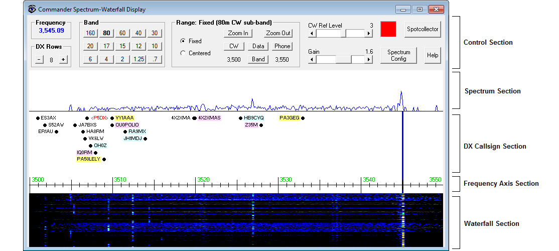
the Spectrum Section displays realtime spectrum data
the DX Callsign Section displays active DX station callsigns
the Frequency Axis Section displays the range of frequencies being displayed in the Spectrum-Waterfall window
the Waterfall Section displays a history of the spectrum section's realtime spectrum data
When controlling an Icom transceiver:
the Frequency panel shows the transceiver's current frequency; if operating split, the current receive frequency is shown.
The frequency's font and background colors are governed by settings in the Frequency Colors panel.
Clicking in this panel makes Commander's Main window visible
the DX Rows panel controls the number of rows of DX Callsigns displayed in the DX Callsign Section
the Band panel contains a button for each band between 160m and 70cm. Commander remembers the last 5 frequencies you visited on each band, and the mode in use for each such visit; this information is stored in a Band Stack associated with each band. If you QSY the radio, and then let it remain on a frequency for longer than the dwell time setting, the new frequency and mode will be saved on the appropriate Band Stack. Clicking a Band panel button sets the radio's frequency to the most recent frequency used on that band, sets its mode to the mode in use at that time, and clears Split; the Band Stack is then advanced, so that clicking the same Band panel button a second time sets the frequency/mode to the next-most-recent frequency/mode used on that band. Using this mechanism, you can QSY to the most recent 5 frequencies. The Band panels in the Bandspread and Spectrum-Waterfall windows share the same Band Stack for each band.
The Range panel can switch the transceiver between Fixed and Centered spectrum tracking modes
When controlling an Icom transceiver,
When the range is Fixed, the Range panel
provides buttons that make the
Spectrum-Waterfall window display the entire Band, or a particular
sub-band:
| Band | sets the range to the entire current band |
| CW | sets the range to the current band's CW sub-band |
| Data | sets the range to the current band's Data sub-band |
| Phone | sets the range to the current band's Phone sub-band |
provides a Zoom In button that when clicked cuts the range in half and centers it on the transceiver's receive frequency
provides a Zoom Out button that when clicked doubles the range and centers it on the transceiver's receive frequency
displays the range's lower frequency to the left of the Band button, and the range's upper frequency to the right of the Band button, and updates these frequencies if they are changed from the transceiver's front panel
When the range is Centered, the Range panel provides buttons that set the range to widths from 5 kHz to 1000 kHz, and updates this selection when the range width is changed from the transceiver's front panel
The Scroll box, if present, enables selection of the radio's SCROLL-C (centered with automatic scrolling) and SCROLL-F (fixed with automatic scrolling) spectrum tracking modes; if the radio supports the SCROLL-C and SCROLL-F tracking modes, check the Use radio's scroll options box on the Spectrum-Waterfall Configuration window.
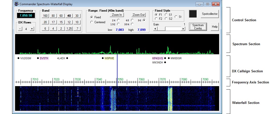
When controlling an Elecraft K4, the Range panel
provides buttons that set the range to 24 KHz, 48 KHz, 96 KHz, 192 KHz, or 384 KHz
provides a Zoom In button that when clicked cuts the range in half
provides a Zoom Out button that when clicked doubles the range
displays the range's low and high frequencies
When the range is Fixed, the
Fixed Style panel governs
how the Range will change as the transceiver frequency approaches it
lower or upper frequency:
Button
Fixed
Range Style
Behavior
F1
Fixed 1
when the
transceiver frequency reaches either end of the range,
the range is shifted in that direction by an amount
equal to the range
F2
Fixed 2
when the transceiver frequency
reaches either end of the range, the range is shifted in
that direction by an amount equal to half the range
S1
Slide 1
when the transceiver frequency
reaches either end of the range,, the range is shifted
smoothly as the frequency continues to move in that
direction.
S2
Slide 2
when the transceiver frequency
approaches either end of the range,, the range is
shifted smoothly as the frequency continues to move in
that direction.
St
Static
when the transceiver frequency
reaches either end of the range, the range does not
change; if the frequency continues to change in that
direction, the frequency indicator will no longer be
visible
If you change the range using the transceiver's
front panel, the Spectrum-Waterfall window's Range
panel will be updated to reflect that change
When controlling an Icom transceiver, the Ref Level slider controls the sensitivity of the transceiver's spectrum display for the current sub-band or band. Changes update the Ref settings in the Spectrum-Waterfall Configuration window's Band Settings panel, and thus are preserved between operating sessions.
The Gain slider specifies a value between 1 and 2 for the current band that expands the magnitude of signals displayed in the Spectrum Section. Changes update the Gain settings in the Spectrum-Waterfall Configuration window's Band Settings panel, and thus are preserved between operating sessions.
The rectangular indicator to the left of the SpotCollector button changes color to indicate the maximum degree of need for any active DX station received by SpotCollector but not visible in the Spectrum-Waterfall window's DX Callsign Section
allowing the mouse cursor to hover over this indicators displays a small popup window showing the most recent and needed, unseen, active DX station's callsign, frequency, mode, and time of arrival
clicking in this indicator resets its color to that corresponding with unneeded
double-clicking in this indicator sets the transceiver's frequency and mode to that of the most recent and needed, unseen, active DX station, and terminates scanning.
Clicking the SpotCollector button on the Spectrum Waterfall window displays SpotCollector's Main window, if SpotCollector is running.
Clicking the Spectrum Config button displays the Spectrum-Waterfall Configuration window
Click the Help button displays this section of Commander's documentation
| Gesture | Action in Spectrum, Frequency Axis, or Waterfall section | Action in DX Callsign section |
| Left click |
|
|
|
Shift-Left click |
|
|
| Control-Left click |
|
|
| Shift-Control-Left click |
|
|
| Alt-Left click |
|
|
| Right click |
|
|
when controlling an Icom transceiver,
if the Mode AutoTrack option is enabled, Commander will set the range to the sub-band associated with the transceiver's mode
if the Mode AutoTrack option is disabled but the Frequency AutoTrack option is enabled, Commander will set the range to the lowest-frequency sub-band that contains the transceiver's frequency (receive frequency, if split); if the transceiver's frequency is not within any of the new band's sub-bands, then Commander will set the range to the entire band.
if neither the Mode AutoTrack nor the Frequency AutoTrack option is enabled, Commander will set the range to the sub-band most recently used on that band
when controlling an Elecraft K4, the width of the range is set to the width most recently used on that band; "fixed vs centered" and Fixed Style remain unchanged
when the Range is Fixed, the Mode AutoTrack option is enabled, and you change the transceiver's mode, Commander will set the range to the sub-band associated with the transceiver's mode
when the Range is Fixed, the Frequency AutoTrack option is enabled, and you QSY out of the current range but still within the current band, Commander will automatically slide the range up or down so that the transceiver's frequency (receive frequency if split) will be visible in the new range
If SpotCollector (version 2.7.4 or later) is running and Commander's Bandspread window or Spectrum-Waterfall window is open, then SpotCollector will automatically send to Commander spots of active DX stations operating on the transceiver's current band that meet SpotCollector's current filter criteria (with the exception that wildcard characters in the Call and DXCC filters are not handled). Commander displays each active DX station on the Bandspread window's slide rule dial and in the Spectrum-Waterfall window unless the active DX station's age exceeds the specified lifetime.
The size of the font used to display active DX stations in the Bandspread window can be specified as a function of its slide rule dial range, making it possible to use larger font sizes with smaller ranges. The size of the font used to display active DX stations in the Spectrum-Waterfall window can be independently specified as a function of its range.
Active DX station callsigns are color-coded based on settings in the Font Colors panel on the Spot Database Display tab of SpotCollector's Configuration window; callsigns known to participate in the ARRL's Logbook of the World (LotW) and/or hold Authenticity Guaranteed membership in eQSL.cc are highlighted as specified in the Background Colors tab on the Spot Database Display tab of SpotCollector's Configuration window.
In the Bandspread window active DX station callsigns that are close together in frequency are separated horizontally to form a list of up to 8 spots. For busy frequencies and a long lifetime, it may be necessary to expand the Bandspread window horizontally to see all of the spots; alternatively, zooming in to a smaller dial range may separate the spots, or a smaller spot font size can be specified. The appearance of a + at the right of a callsign means that additional callsigns have been spotted on or near the frequency.
In the Spectrum-Waterfall window, active DX station callsigns that are close together in frequency are separated vertically in up to 32 rows. For busy frequencies and a long lifetime, it may be necessary to expand the Spectrum-Waterfall window horizontally to see all of the spots; alternatively, zooming in to a smaller dial range may separate the spots, or a smaller spot font size can be specified. The appearance of a + below a callsign means that additional callsigns have been spotted on or near the frequency; you can increase or decrease the number of rows displayed via the DX Rows panel on Spectrum-Waterfall window.
allowing the mouse cursor to hover over an active DX station callsign displays a small popup window showing the spot's callsign, transmit frequency, QSX (listening) frequency if operating split, mode, UTC time last spotted, LotW participation, areas from which the station was spotted, and spot notes
clicking on an active DX station callsign in the Bandspread or Spectrum-Waterfall window will
if the selected callsign is operating in PSK31, PSK63, or PSK125
if the specified Digital Mode Application is running, convey the frequency and mode to that application, which will direct Commander to QSY to the optimal frequency and mode
if the specified Digital Mode Application is not running or no Digital Mode Application is specified, will direct Commander to QSY to the callsign's frequency in the mode specified in the PSK mode if no DMA, K1JT mode if no SpotCollector subpanel
if the selected callsign is operating in a K1JT mode like FT8
if SpotCollector (version 9.8.3 or later) is running and connected to an instance of WJST-X, convey the callsign, frequency, and mode to that instance, which will direct Commander to QSY to the optimal frequency and mode
if SpotCollector is not running and connected to an instance of WJST-X, will direct Commander to QSY to the callsign's frequency in the mode specified in the PSK mode if no DMA, K1JT mode if no SpotCollector subpanel
if the selected callsign is operating in RTTY
if the specified Digital Mode Application is running, convey the frequency and mode to that application, which will direct Commander to QSY to the optimal frequency and mode
if the specified Digital Mode Application is not running or no Digital Mode Application is specified, will direct Commander to QSY to the callsign's frequency in the mode specified in the RTTY Mode if no DMA subpanel
if the selected callsign is operating in CW
if the CW Mode subpanel is set to CW, QSY to the selected callsign's frequency in CW mode
if the CW Mode subpanel is set to CW-R, QSY to the selected callsign's frequency in CW-R (reversed) mode
if the CW Mode subpanel is set to CW via DMA, convey callsign, frequency, and mode to the specified Digital Mode Application, which will QSY to the optimal frequency and mode
if the station is operating split and the set Xcvr split option is enabled
set the radio's VFOs to the appropriate transmit and receive frequencies,
configure the radio for split operations (enable split and dual mode, if available)
if the selected callsign is operating in SSB and the Phone modes subpanel's is set to SSB via DMA box is checked, convey callsign, frequency, and mode to the specified Digital Mode Application, which will QSY to the optimal frequency and mode, otherwise QSY to the station's frequency in either USB mode (if the frequency is above 10 Mhz) or LSB mode (if the frequency is below 10 Mhz)
if the station is operating split and the set Xcvr split option is enabled
set the radio's VFOs to the appropriate transmit and receive frequencies,
configure the radio for split operations (enable split and dual mode, if available)
if the selected callsign is operating in FM and the Phone modes subpanel's is set to FM via DMA box is checked, convey callsign, frequency, and mode to the specified Digital Mode Application, which will QSY to the optimal frequency and mode, otherwise QSY to the station's frequency in FM mode
if the station is operating split and the set Xcvr split option is enabled
set the radio's VFOs to the appropriate transmit and receive frequencies,
configure the radio for split operations (enable split and dual mode, if available)
if the selected callsign is operating in AM and the Phone modes subpanel's is set to AM via DMA box is checked, convey callsign, frequency, and mode to the specified Digital Mode Application, which will QSY to the optimal frequency and mode, otherwise QSY to the station's frequency in AM mode
if the station is operating split and the set Xcvr split option is enabled
set the radio's VFOs to the appropriate transmit and receive frequencies,
configure the radio for split operations (enable split and dual mode, if available)
direct DXKeeper (if running) to
initialize its Capture window with the DX spot's callsign, frequency, mode, and gridsquare (if available)
filter its Log Page Display to show all previous QSOs with the DX spot's callsign or DXCC entity, as specified by the Log Filter setting
if both DXView and DXKeeper are running
direct DXView to perform a lookup of the DX spot callsign
if the CTRL key was depressed while clicking on the DX spot, rotate the antenna to the short path bearing to the spotted station
if the ALT key was depressed while clicking on the DX spot, rotate the antenna to the long path bearing to the spotted station
double-clicking an active DX station callsign in the Bandspread window performs all of the operations described above under single-clicking, and then reduces the slide rule dial range by one step, unless the range is already 1 kHz.
When the radio QSYs from one band to another with the Bandspread and/or Spectrum-Waterfall windows open, Commander clears the active DX station callsigns from the Bandspread window and Spectrum-Waterfall window, and SpotCollector sends Commander each Spot Database entry on the new band that meet its current filter criteria (subject to the above-mentioned wildcard character limitation). Thus Commander always displays that subset of SpotCollector's filtered Spot Database entries that are operating in the range of frequencies shown on the Bandspread window and on the Spectrum-Waterfall window
Commander displays a rectangular indicator in the lower-left corner of the Bandspread window, and in the upper-right corner of the Spectrum-Waterfall window. The color of the rectangle in the Bandspread window indicates the maximum degree of need for any active DX station received by SpotCollector but not visible on the Bandspread window's slide rule dial. Similarly, the color of the rectangle in the Spectrum-Waterfall window indicates the maximum degree of need for any active DX stations received by SpotCollector but not visible on the Waterfall-Spectrum window.
allowing the mouse cursor to hover over one of these rectangular indicators displays a small popup window showing the most recent and needed unseen active DX station's callsign, frequency, mode, and time of arrival
clicking a rectangular indicator resets its color to that corresponding with unneeded
double-clicking a rectangular indicator sets the radio's frequency and mode to that of the most recent and needed unseen active DX station, and terminates scanning.
Clicking the SpotCollector button on the Bandspread window or on the Spectrum Waterfall window activates SpotCollector's Main window, if SpotCollector is running.
The memory used to maintain and display active DX spots is freed when the Bandspread window and Spectrum-Waterfall windows are both closed.