|
Size: 3624
Comment:
|
← Revision 59 as of 2024-04-10 22:18:59 ⇥
Size: 3643
Comment:
|
| Deletions are marked like this. | Additions are marked like this. |
| Line 29: | Line 29: |
| * Icom: IC-705, IC-7100, IC-7300, IC-7410, IC-7600, IC-7610, IC-7700, IC-7800, IC-7850, IC-7851, IC-9100, IC-9700 | * Icom: IC-705, IC-7100, IC-7300 (current firmware), IC-7410, IC-7600, IC-7610, IC-7700, IC-7800, IC-7850, IC-7851, IC-9100, IC-9700 |
Configuring the CW Keying connection
The Keying panel on the CW tab of WinWarbler's Configuration window specifies how a CW keying signal is to be generated; there are 5 basic alternatives:
by a serial port RTS or DTR signal, employing RS-232 voltage levels (+12 VDC, -12 VDC); in this configuration, CW timing is controlled by Windows, and thus may vary with CPU and memory load
by a parallel port data Data, Init, or Select signal, employing TTL voltage levels (+5 VDC, 0 VDC); in this configuration, CW timing is controlled by Windows, and thus may vary with CPU and memory load
by a Winkeyer circuit (or by an interface device containing this circuit) connected by an RS232 cable
by a transceiver that can be directed to transmit CW via CAT command and that is being controlled by Commander
- Configuration
set the Keying panel to Xcvr Ctrl App
- automatic switching between reception and transmission may also require configuring your transceiver for CW Break-In operation
- Transceivers
- DZKit Sienna
Elecraft: K2, K3, K3S, KX2, KX3, or K4 (additional configuration instructions for K3 family and K4 transceivers are here); note: enable the transceiver's VOX function
FlexRadio: all models running PowerSDR or SmartSDR
- Icom: IC-705, IC-7100, IC-7300 (current firmware), IC-7410, IC-7600, IC-7610, IC-7700, IC-7800, IC-7850, IC-7851, IC-9100, IC-9700
enable the transceiver's Break-in function
- Icom transceivers provide a command that conveys up to 30 characters to be sent in CW, but provide no indication of how many CW characters remain un-transmitted. Commander will break messages larger than 30 characters into multiple commands, but the transceiver may reject commands if sufficient buffering in its microprocessor's memory is not available
- Kenwood: TS-480, TS-570, TS-590, TS-870, TS-990, TS-2000
TenTec: Orion
- Configuration
Some transceivers require their Break-in function to be enabled in order to transmit CW via the means described above.
RTS or DTR Circuit Details
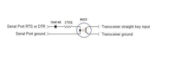
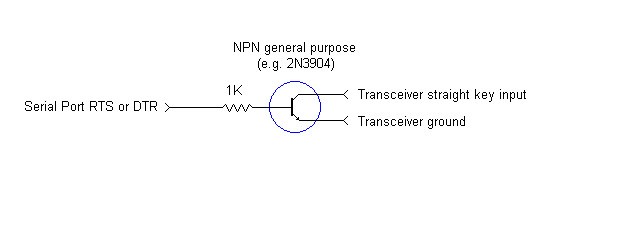
If you use a serial port RTS or DTR signal, an external circuit is required is required to drive your transceiver's straight key input:
- a simple opto-isolator circuit
- a simple NPN transistor circuit
MORTTY - a CW and RTTY interface
N6TV offers a fully assembled breakout box that provides four keying circuits as well as one or two internal FTDI USB-to-Serial adapters and all required cables
- a section of a commercial interface
Changing a Serial Port's COM Number
If necessary, you can change the COM port number that Windows assigns to a USB-to-serial-port adaptor.
Setting up CW, Phone, PSK, and RTTY Operation


